Mantis 10 Single Drive 48V 800W Wiring Diagram Guide SGTEC07

Mantis 10 Single Drive 48V 800W Wiring Diagram Guide SGTEC07

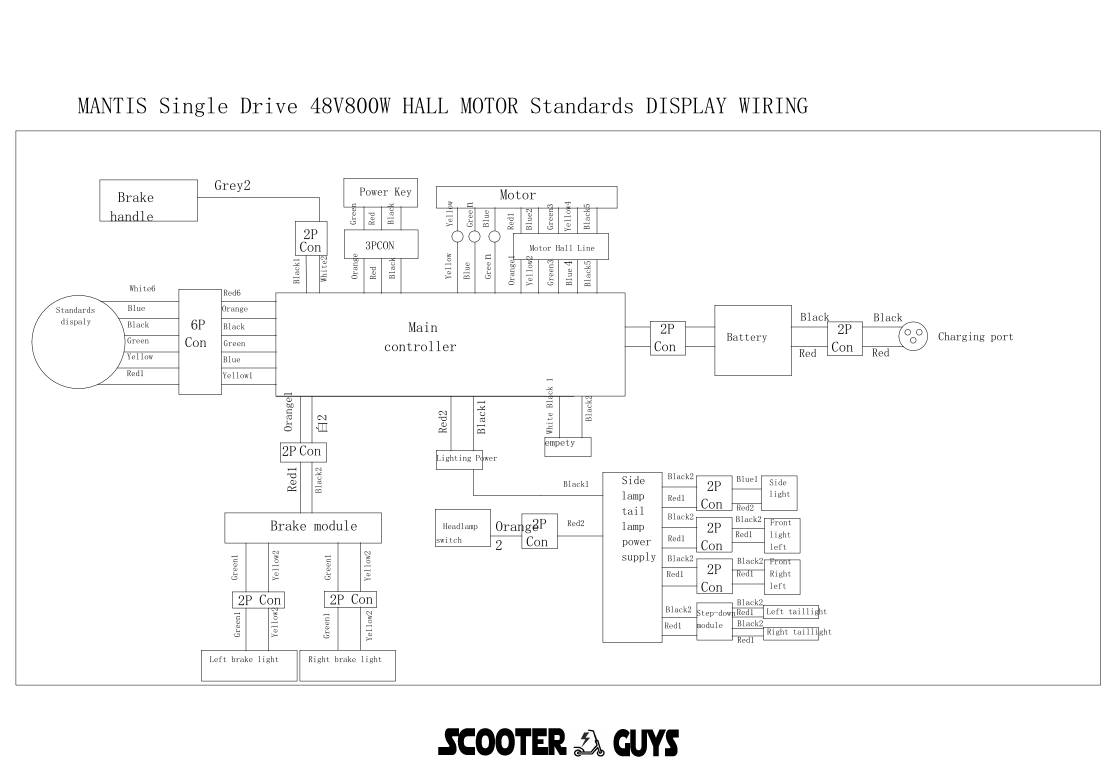
This guide provides a comprehensive wiring diagram for the Mantis 10 electric scooter with a single drive 48V 800W brushless motor with a hall sensor. The wiring involves the standard display, main controller, various connectors, brake module, brake handle, headlamp, power key, 48V battery, and charge port.

Components:

  1. Standard Display:
    • Connection Type: 6-pin connector (6P)
  2. Main Controller:
    • Function: Central processing unit for controlling the scooter
  3. Motor:
    • Model: 800W Brushless Motor with Hall Sensor
    • Voltage: 48V
  4. Brake Module:
    • Connection Type: 2-pin connector (2P)
  5. Brake Handle:
    • Connection Type: 2-pin connector (2P)
  6. Headlamp:
    • Connection Type: 2-pin connector (2P)
  7. Power Key:
    • Connection Type: 3-pin connector (3P)
  8. 48V Battery:
    • Connection Type: 2-pin connector (2P)
  9. Charge Port:
    • Connection Type: 2-pin connector (2P)
  10. Motor Hall Line:
  • Connection Type: Hall sensor line

Wiring Diagram:

Below is a detailed step-by-step guide to wiring each component:

  1. Connecting the Standard Display to the Main Controller:
    • The standard display uses a 6-pin connector (6P).
    • Wire color coding and pin configuration:
      • Red (Power +5V): Connect to the +5V power output on the main controller.
      • Black (Ground): Connect to the ground terminal on the main controller.
      • Green (Signal 1): Connect to the first signal input on the main controller.
      • Yellow (Signal 2): Connect to the second signal input on the main controller.
      • Blue (Communication): Connect to the data communication port on the main controller.
      • White (Backlight Control): Connect to the backlight control input on the main controller.
  2. Connecting the Brake Module to the Main Controller:
    • The brake module uses a 2-pin connector (2P).
    • Wire color coding and pin configuration:
      • Red (Power +5V): Connect to the +5V power output on the main controller.
      • Black (Ground): Connect to the ground terminal on the main controller.
  3. Connecting the Brake Handle to the Main Controller:
    • The brake handle uses a 2-pin connector (2P).
    • Wire color coding and pin configuration:
      • Red (Brake Signal): Connect to the brake signal input on the main controller.
      • Black (Ground): Connect to the ground terminal on the main controller.
  4. Connecting the Headlamp to the Main Controller:
    • The headlamp uses a 2-pin connector (2P).
    • Wire color coding and pin configuration:
      • Red (Power +): Connect to the headlamp power output on the main controller.
      • Black (Ground): Connect to the ground terminal on the main controller.
  5. Connecting the Power Key to the Main Controller:
    • The power key uses a 3-pin connector (3P).
    • Wire color coding and pin configuration:
      • Red (Power +): Connect to the main power input on the main controller.
      • Black (Ground): Connect to the ground terminal on the main controller.
      • Green (Signal): Connect to the power key signal input on the main controller.
  6. Connecting the 48V Battery to the Main Controller:
    • The 48V battery uses a 2-pin connector (2P).
    • Wire color coding and pin configuration:
      • Red (Battery +): Connect to the battery positive terminal on the main controller.
      • Black (Battery -): Connect to the ground terminal on the main controller.
  7. Connecting the Charge Port to the Main Controller:
    • The charge port uses a 2-pin connector (2P).
    • Wire color coding and pin configuration:
      • Red (Charging +): Connect to the charging positive terminal on the main controller.
      • Black (Charging -): Connect to the ground terminal on the main controller.
  8. Connecting the Motor Hall Line to the Main Controller:
    • The motor hall line connects the hall sensors of the motor to the main controller.
    • Hall sensor connection details:
      • Red (Hall Power +5V): Connect to the +5V hall sensor power output on the main controller.
      • Black (Ground): Connect to the hall sensor ground terminal on the main controller.
      • Green (Hall Sensor A): Connect to the hall sensor A input on the main controller.
      • Yellow (Hall Sensor B): Connect to the hall sensor B input on the main controller.
      • Blue (Hall Sensor C): Connect to the hall sensor C input on the main controller.

Wiring Connections:

  1. Standard Display to Main Controller (6P):
    • Red: +5V Power
    • Black: Ground
    • Green: Signal 1
    • Yellow: Signal 2
    • Blue: Communication
    • White: Backlight Control
  2. Brake Module to Main Controller (2P):
    • Red: +5V Power
    • Black: Ground
  3. Brake Handle to Main Controller (2P):
    • Red: Brake Signal
    • Black: Ground
  4. Headlamp to Main Controller (2P):
    • Red: Power +
    • Black: Ground
  5. Power Key to Main Controller (3P):
    • Red: Power +
    • Black: Ground
    • Green: Signal
  6. 48V Battery to Main Controller (2P):
    • Red: Battery +
    • Black: Battery –
  7. Charge Port to Main Controller (2P):
    • Red: Charging +
    • Black: Charging –
  8. Motor Hall Line to Main Controller:
    • Red: +5V Power
    • Black: Ground
    • Green: Hall Sensor A
    • Yellow: Hall Sensor B
    • Blue: Hall Sensor C

Tips:

  • Ensure all connections are secure and insulated to prevent short circuits.
  • Follow the color-coding strictly to avoid any miswiring.
  • Refer to the user manual for specific details regarding your model.
  • Double-check all connections before powering on the scooter to ensure everything is correctly wired.

This detailed wiring diagram and guide should help in successfully connecting and configuring the components of your Mantis 10 electric scooter with a single drive 48V 800W motor.

Read more

Essential Escooter and E-bike Accessories from Scooter Guys

Essential Escooter and E-bike Accessories from Scooter Guys

Electric scooters are becoming increasingly popular in the UK, and an essential mode of transport for commuting, with their rise in popularity comes a demand for accessories to enhance the riding experience. There are a variety of accessories available on the market, but some stand out as the best.

HELMETS

a helmet is an essential accessory for any electric scooter rider. Safety should always be a top priority, and wearing a helmet can prevent serious head injuries in case of an accident. All scooter guys helmets are check with the following regulations

  • British Standard BS 6658:1985 and carry the BSI Kitemark
  • UNECE Regulation 22.05
  • A European Economic Area member standard offering at least the same safety and protection as BS 6658:1985, and carry a mark equivalent to the BSI Kitemark

PHONE MOUNT

, a phone mount is another useful accessory. Scooter guys has a range of phone mounts, which have been tested in the roughest terrain and wet weather, the phone mounts are ideal for GPS navigation and music streaming apps readily available on smartphones, having your phone mounted on your escooter’s handlebars makes it easier to access these features while riding.

LIGHTS

lights and reflectors are important accessories for night-time riding. They increase visibility and make it easier for other road users to see you, scooter guys have in stock latest powerful CRE LED chip headlights, with they powerful beam, lights up darkest of trail.

STORAGE

storage options such as baskets or bags can be useful for carrying items such as spare battery pack or phones while riding.

Overall, these accessories can greatly improve the safety and convenience of electric scooter riding in the UK

https://scooterguys.co.uk/products/

https://www.ruroc.com/en_gb/motorcycle/motorcycle-helmets.html

Read more

E-scooter and E-bike Spare Parts

Read more

Design and Testing of Composite Materials for the EV Industry

Design and Testing of Composite Materials for the EV Industry

The popularity of electric vehicles has increased in recent years. The design and testing of electric scooters (e-scooters) and e-bikes have been revolutionized by the use of lightweight, high-strength, and durable composite materials. These materials are created by combining two or more different materials to form a new material with improved properties. Compared to traditional materials such as steel and aluminium, composite materials offer several advantages, including lower weight and greater strength.

Designing with Composite Materials

During the design phase, the appropriate composite material must be carefully selected by engineers for each component of the vehicle. For instance, carbon fiber composites may be used for the frame to reduce weight while maintaining strength. Kevlar composites may be used for impact-resistant components such as fenders. A comprehensive scientific article on future composite materials such as plastics, carbon fibre, and composite metals in the manufacturing of e-scooters and e-bikes would cover the history of these materials, their current use in the industry, the trend of future development and applications, and new materials and manufacturing technologies enabling advancements.

Testing Composite Materials

It is crucial to ensure that these composite materials meet safety standards and perform as expected under various conditions through testing. This includes testing for strength, stiffness, fatigue resistance, impact resistance, and environmental factors such as temperature and humidity. Non-destructive testing (NDT) techniques such as ultrasonic testing, radiography, magnetic particle inspection, and dye penetrant inspection are used to determine tolerances and safety of finished components. These techniques are used to detect defects such as cracks, voids, and inclusions in the finished components.

The Future of Composite Materials

The use of composite materials in e-scooter and e-bike design has revolutionized the industry by allowing for lighter weight vehicles with increased durability. Proper design and testing of these materials are essential to ensure safe and reliable transportation options for consumers.

The future of composite materials in the manufacturing of e-scooters and e-bikes looks promising. Advancements in the development and application of carbon fibre composites are being enabled by new materials and manufacturing technologies. The potential revolution for the composite industry is also being explored through 3D printing of carbon fibre composites.

Scooter Guys is a company that supplies OEM components to maintain and keep roadworthy this mode of transport. By using high-quality OEM components, e-scooter operators can ensure that their vehicles remain in good condition for longer, reducing their environmental impact.

https://www.esma.bike/

https://www.iso.org/

https://www.scooterguys.com/blog

Read more