Electric Scooter Parts: Unlocking Optimal Performance

Electric Scooter Parts: Unlocking Optimal Performance

Electric scooters, commonly known as e-scooters, have rapidly become a favored mode of urban transportation. Their compact size, ease of use, and eco-friendly nature make them ideal for zipping through city streets. However, like any mechanical device, e-scooters rely on various components to function effectively. Whether you’re commuting to work or cruising around town, understanding the essential parts of your electric scooter is vital for preventing breakdowns and maximizing performance. This essay delves into the key components that power your e-scooter and discusses how Scooter Guys, a leading supplier in the UK, offers a comprehensive range of escooter spares and ebike parts to keep your ride in top condition.

Key Components for Optimal Performance

When it comes to getting the most out of your electric scooter, several critical components play a significant role in ensuring optimal performance. These components include the battery, motor, wheels and tires, brakes, and frame design. Each part contributes to the scooter’s overall functionality and performance, making it essential to understand and maintain them properly.

1. The Battery: The Heart of Your E-Scooter

The battery is arguably the most crucial component of your electric scooter. It powers the motor and all electrical systems, determining how far and how fast you can travel. Lithium-ion batteries are particularly popular due to their lightweight nature and long lifespan. Investing in a high-quality battery from Scooter Guys can significantly enhance your scooter’s range and overall efficiency, ensuring that you can travel longer distances without worrying about running out of power.

2. The Motor: Driving Performance and Speed

The motor is another vital component that directly impacts your e-scooter’s performance. The type and power of the motor can influence acceleration, top speed, and the ability to handle inclines. Brushless motors, which are favored for their efficiency and low maintenance requirements, are available at Scooter Guys. Upgrading to a more powerful motor can give your scooter the extra boost it needs to tackle steeper hills or achieve higher speeds, providing a more exhilarating riding experience.

3. Wheels and Tires: Enhancing Ride Comfort and Stability

Wheels and tires are essential for ensuring a smooth and stable ride. The right tire pressure and tread pattern can make a significant difference in how your scooter handles various terrains. Scooter Guys offers a wide selection of wheels and tires, including options for both pneumatic (air-filled) and solid tires. Opting for larger wheels or specialized tires can improve stability and reduce rolling resistance, making your ride more comfortable and efficient, especially during longer commutes.

4. Braking Systems: Prioritizing Safety

Safety should always be a top priority, and a reliable braking system is crucial for any e-scooter. Scooter Guys provides a range of brake components, including brake pads, discs, and hydraulic disc brakes, which offer superior stopping power compared to standard mechanical brakes. Upgrading your braking system can enhance your scooter’s responsiveness, particularly in wet or challenging conditions, ensuring that you can stop quickly and safely when needed.

5. Frame Design and Weight Distribution: Balancing Comfort and Handling

The frame of your e-scooter plays a significant role in its handling and overall comfort. A well-balanced scooter frame, coupled with proper weight distribution, can improve your riding experience by providing better control and stability. Scooter Guys offers various frame components, including handlebars, stems, and suspension systems, allowing you to customize your scooter for a more comfortable and personalized ride. By making these upgrades, you can transform your scooter into a ride that not only performs well but also feels great to use.

Read more

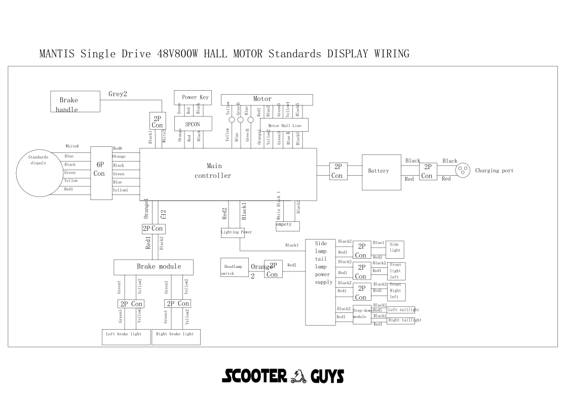
Mantis 10 Single Drive 48V 800W Wiring Diagram Guide SGTEC07

Mantis 10 Single Drive 48V 800W Wiring Diagram Guide SGTEC07

This guide provides a comprehensive wiring diagram for the Mantis 10 electric scooter with a single drive 48V 800W brushless motor with a hall sensor. The wiring involves the standard display, main controller, various connectors, brake module, brake handle, headlamp, power key, 48V battery, and charge port.

Components:

  1. Standard Display:
    • Connection Type: 6-pin connector (6P)
  2. Main Controller:
    • Function: Central processing unit for controlling the scooter
  3. Motor:
    • Model: 800W Brushless Motor with Hall Sensor
    • Voltage: 48V
  4. Brake Module:
    • Connection Type: 2-pin connector (2P)
  5. Brake Handle:
    • Connection Type: 2-pin connector (2P)
  6. Headlamp:
    • Connection Type: 2-pin connector (2P)
  7. Power Key:
    • Connection Type: 3-pin connector (3P)
  8. 48V Battery:
    • Connection Type: 2-pin connector (2P)
  9. Charge Port:
    • Connection Type: 2-pin connector (2P)
  10. Motor Hall Line:
  • Connection Type: Hall sensor line

Wiring Diagram:

Below is a detailed step-by-step guide to wiring each component:

  1. Connecting the Standard Display to the Main Controller:
    • The standard display uses a 6-pin connector (6P).
    • Wire color coding and pin configuration:
      • Red (Power +5V): Connect to the +5V power output on the main controller.
      • Black (Ground): Connect to the ground terminal on the main controller.
      • Green (Signal 1): Connect to the first signal input on the main controller.
      • Yellow (Signal 2): Connect to the second signal input on the main controller.
      • Blue (Communication): Connect to the data communication port on the main controller.
      • White (Backlight Control): Connect to the backlight control input on the main controller.
  2. Connecting the Brake Module to the Main Controller:
    • The brake module uses a 2-pin connector (2P).
    • Wire color coding and pin configuration:
      • Red (Power +5V): Connect to the +5V power output on the main controller.
      • Black (Ground): Connect to the ground terminal on the main controller.
  3. Connecting the Brake Handle to the Main Controller:
    • The brake handle uses a 2-pin connector (2P).
    • Wire color coding and pin configuration:
      • Red (Brake Signal): Connect to the brake signal input on the main controller.
      • Black (Ground): Connect to the ground terminal on the main controller.
  4. Connecting the Headlamp to the Main Controller:
    • The headlamp uses a 2-pin connector (2P).
    • Wire color coding and pin configuration:
      • Red (Power +): Connect to the headlamp power output on the main controller.
      • Black (Ground): Connect to the ground terminal on the main controller.
  5. Connecting the Power Key to the Main Controller:
    • The power key uses a 3-pin connector (3P).
    • Wire color coding and pin configuration:
      • Red (Power +): Connect to the main power input on the main controller.
      • Black (Ground): Connect to the ground terminal on the main controller.
      • Green (Signal): Connect to the power key signal input on the main controller.
  6. Connecting the 48V Battery to the Main Controller:
    • The 48V battery uses a 2-pin connector (2P).
    • Wire color coding and pin configuration:
      • Red (Battery +): Connect to the battery positive terminal on the main controller.
      • Black (Battery -): Connect to the ground terminal on the main controller.
  7. Connecting the Charge Port to the Main Controller:
    • The charge port uses a 2-pin connector (2P).
    • Wire color coding and pin configuration:
      • Red (Charging +): Connect to the charging positive terminal on the main controller.
      • Black (Charging -): Connect to the ground terminal on the main controller.
  8. Connecting the Motor Hall Line to the Main Controller:
    • The motor hall line connects the hall sensors of the motor to the main controller.
    • Hall sensor connection details:
      • Red (Hall Power +5V): Connect to the +5V hall sensor power output on the main controller.
      • Black (Ground): Connect to the hall sensor ground terminal on the main controller.
      • Green (Hall Sensor A): Connect to the hall sensor A input on the main controller.
      • Yellow (Hall Sensor B): Connect to the hall sensor B input on the main controller.
      • Blue (Hall Sensor C): Connect to the hall sensor C input on the main controller.

Wiring Connections:

  1. Standard Display to Main Controller (6P):
    • Red: +5V Power
    • Black: Ground
    • Green: Signal 1
    • Yellow: Signal 2
    • Blue: Communication
    • White: Backlight Control
  2. Brake Module to Main Controller (2P):
    • Red: +5V Power
    • Black: Ground
  3. Brake Handle to Main Controller (2P):
    • Red: Brake Signal
    • Black: Ground
  4. Headlamp to Main Controller (2P):
    • Red: Power +
    • Black: Ground
  5. Power Key to Main Controller (3P):
    • Red: Power +
    • Black: Ground
    • Green: Signal
  6. 48V Battery to Main Controller (2P):
    • Red: Battery +
    • Black: Battery –
  7. Charge Port to Main Controller (2P):
    • Red: Charging +
    • Black: Charging –
  8. Motor Hall Line to Main Controller:
    • Red: +5V Power
    • Black: Ground
    • Green: Hall Sensor A
    • Yellow: Hall Sensor B
    • Blue: Hall Sensor C

Tips:

  • Ensure all connections are secure and insulated to prevent short circuits.
  • Follow the color-coding strictly to avoid any miswiring.
  • Refer to the user manual for specific details regarding your model.
  • Double-check all connections before powering on the scooter to ensure everything is correctly wired.

This detailed wiring diagram and guide should help in successfully connecting and configuring the components of your Mantis 10 electric scooter with a single drive 48V 800W motor.

Read more

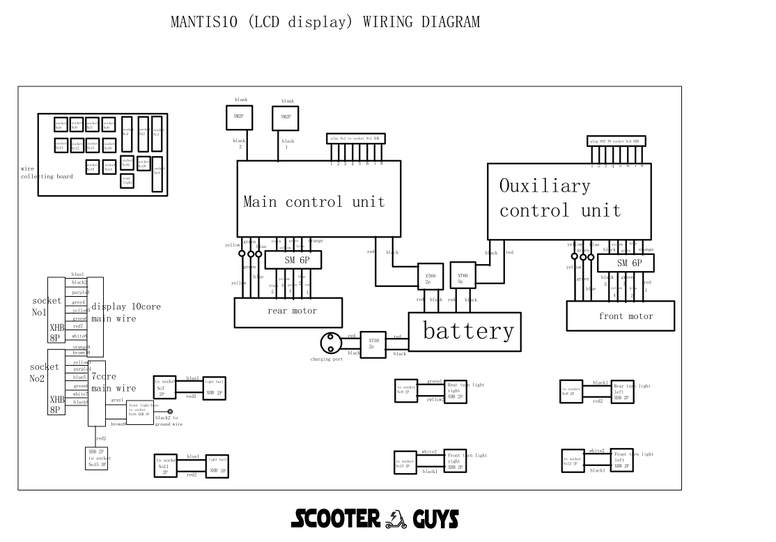
Mantis 10 Electric Scooter Wiring Diagram Guide SGTEC06

Mantis 10 Electric Scooter Wiring Diagram Guide SGTEC06

This guide provides a detailed wiring diagram for the Mantis 10 electric scooter, focusing on connecting the LCD display, Hub Board SG134, main control unit, auxiliary control unit, 10-core and 7-core main wires, and the motor.

Components:

  1. LCD Display:
    • Model: Generic Mantis 10 Display
    • Connection Type: 10-core wire
  2. Hub Board SG134:
    • Functions: Distribution of signals and power to various components
  3. Main Control Unit (MCU):
    • Function: Central processing unit for controlling the scooter
  4. Auxiliary Control Unit (ACU):
    • Function: Assists the MCU with additional control features
  5. 10-Core Main Wire SG790B:
    • Connection: Between the display and MCU
  6. 7-Core Main Wire SG790A:
    • Connection: Between the hub board and MCU
  7. Motor:
    • Model: 10-inch 60V 1100W SG798B
    • Connection: Wired to the MCU via hub board

Wiring Diagram:

Below is a step-by-step guide to wiring each component:

  1. Connecting the LCD Display to the Main Control Unit:
    • The LCD display uses a 10-core main wire (SG790B).
    • Wire color coding and pin configuration:
      • Red (Power): Connect to the 60V positive terminal.
      • Black (Ground): Connect to the ground terminal.
      • Green (Signal): Connect to the MCU’s signal input.
      • Yellow (Throttle Signal): Connect to the throttle control input on the MCU.
      • Blue (Brake Signal): Connect to the brake input on the MCU.
      • White (Speed Sensor): Connect to the speed sensor input on the MCU.
      • Brown (Auxiliary Power): Connect to the auxiliary power input on the MCU.
      • Purple (Light Control): Connect to the light control input on the MCU.
      • Orange (Communication): Connect to the data communication port on the MCU.
      • Gray (Other Signal): Connect as required for additional functions.
  2. Connecting the Hub Board SG134 to the Main Control Unit:
    • The hub board connects to the MCU via the 7-core main wire (SG790A).
    • Wire color coding and pin configuration:
      • Red (Power): Connect to the 60V positive terminal.
      • Black (Ground): Connect to the ground terminal.
      • Green (Signal): Connect to the hub board signal input.
      • Yellow (Throttle Signal): Connect to the throttle control input on the hub board.
      • Blue (Brake Signal): Connect to the brake input on the hub board.
      • White (Speed Sensor): Connect to the speed sensor input on the hub board.
      • Brown (Auxiliary Power): Connect to the auxiliary power input on the hub board.
  3. Connecting the Motor to the Main Control Unit via Hub Board:
    • The motor (SG798B) connects to the hub board which then connects to the MCU.
    • Motor connection details:
      • Red (Motor Power +): Connect to the motor power output on the hub board.
      • Black (Motor Power -): Connect to the ground terminal on the hub board.
      • Green (Hall Sensor A): Connect to the corresponding hall sensor input on the hub board.
      • Yellow (Hall Sensor B): Connect to the corresponding hall sensor input on the hub board.
      • Blue (Hall Sensor C): Connect to the corresponding hall sensor input on the hub board.
      • White (Temperature Sensor): Connect to the temperature sensor input on the hub board.
      • Brown (Other Signal): Connect as required for additional motor functions.
  4. Auxiliary Control Unit (ACU):
    • The ACU assists with additional control features and connects to the MCU and hub board as necessary.
    • Ensure all signal and power lines from the ACU are appropriately connected to the MCU and hub board.

Tips:

  • Ensure all connections are secure and insulated to prevent short circuits.
  • Follow the color-coding strictly to avoid any miswiring.
  • Refer to the user manual for specific details regarding your model.

This detailed wiring diagram and guide should help in successfully connecting and configuring the components of your Mantis 10 electric scooter.


Read more