Search
Close this search box.
Home electric scooter Mantis 10 Electric Scooter Wiring Diagram Guide SGTEC06

Mantis 10 Electric Scooter Wiring Diagram Guide SGTEC06

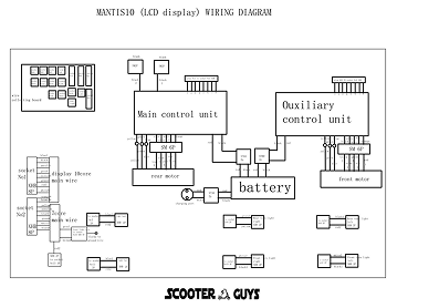
mantis-10-electrical-wiring-diagram-scooterguys

Mantis 10 Electric Scooter Wiring Diagram Guide SGTEC06

This guide provides a detailed wiring diagram for the Mantis 10 electric scooter, focusing on connecting the LCD display, Hub Board SG134, main control unit, auxiliary control unit, 10-core and 7-core main wires, and the motor.

Components:

  1. LCD Display:
    • Model: Generic Mantis 10 Display
    • Connection Type: 10-core wire
  2. Hub Board SG134:
    • Functions: Distribution of signals and power to various components
  3. Main Control Unit (MCU):
    • Function: Central processing unit for controlling the scooter
  4. Auxiliary Control Unit (ACU):
    • Function: Assists the MCU with additional control features
  5. 10-Core Main Wire SG790B:
    • Connection: Between the display and MCU
  6. 7-Core Main Wire SG790A:
    • Connection: Between the hub board and MCU
  7. Motor:
    • Model: 10-inch 60V 1100W SG798B
    • Connection: Wired to the MCU via hub board

Wiring Diagram:

Below is a step-by-step guide to wiring each component:

  1. Connecting the LCD Display to the Main Control Unit:
    • The LCD display uses a 10-core main wire (SG790B).
    • Wire color coding and pin configuration:
      • Red (Power): Connect to the 60V positive terminal.
      • Black (Ground): Connect to the ground terminal.
      • Green (Signal): Connect to the MCU’s signal input.
      • Yellow (Throttle Signal): Connect to the throttle control input on the MCU.
      • Blue (Brake Signal): Connect to the brake input on the MCU.
      • White (Speed Sensor): Connect to the speed sensor input on the MCU.
      • Brown (Auxiliary Power): Connect to the auxiliary power input on the MCU.
      • Purple (Light Control): Connect to the light control input on the MCU.
      • Orange (Communication): Connect to the data communication port on the MCU.
      • Gray (Other Signal): Connect as required for additional functions.
  2. Connecting the Hub Board SG134 to the Main Control Unit:
    • The hub board connects to the MCU via the 7-core main wire (SG790A).
    • Wire color coding and pin configuration:
      • Red (Power): Connect to the 60V positive terminal.
      • Black (Ground): Connect to the ground terminal.
      • Green (Signal): Connect to the hub board signal input.
      • Yellow (Throttle Signal): Connect to the throttle control input on the hub board.
      • Blue (Brake Signal): Connect to the brake input on the hub board.
      • White (Speed Sensor): Connect to the speed sensor input on the hub board.
      • Brown (Auxiliary Power): Connect to the auxiliary power input on the hub board.
  3. Connecting the Motor to the Main Control Unit via Hub Board:
    • The motor (SG798B) connects to the hub board which then connects to the MCU.
    • Motor connection details:
      • Red (Motor Power +): Connect to the motor power output on the hub board.
      • Black (Motor Power -): Connect to the ground terminal on the hub board.
      • Green (Hall Sensor A): Connect to the corresponding hall sensor input on the hub board.
      • Yellow (Hall Sensor B): Connect to the corresponding hall sensor input on the hub board.
      • Blue (Hall Sensor C): Connect to the corresponding hall sensor input on the hub board.
      • White (Temperature Sensor): Connect to the temperature sensor input on the hub board.
      • Brown (Other Signal): Connect as required for additional motor functions.
  4. Auxiliary Control Unit (ACU):
    • The ACU assists with additional control features and connects to the MCU and hub board as necessary.
    • Ensure all signal and power lines from the ACU are appropriately connected to the MCU and hub board.

Tips:

  • Ensure all connections are secure and insulated to prevent short circuits.
  • Follow the color-coding strictly to avoid any miswiring.
  • Refer to the user manual for specific details regarding your model.

This detailed wiring diagram and guide should help in successfully connecting and configuring the components of your Mantis 10 electric scooter.


Related Post

Leave a Reply

Your email address will not be published. Required fields are marked *