Mantis 10 Electric Scooter Wiring Diagram Guide SGTEC06

Mantis 10 Electric Scooter Wiring Diagram Guide SGTEC06
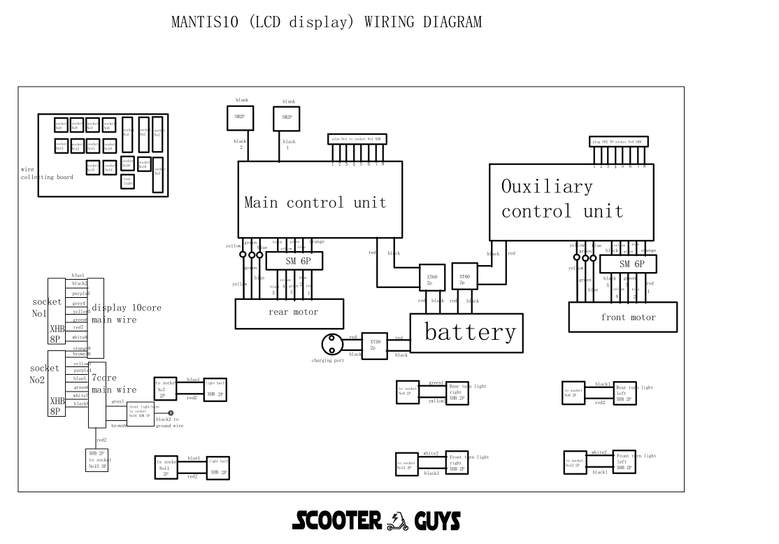
This guide provides a detailed wiring diagram for the Mantis 10 electric scooter, focusing on connecting the LCD display, Hub Board SG134, main control unit, auxiliary control unit, 10-core and 7-core main wires, and the motor.
Components:
- LCD Display:
- Model: Generic Mantis 10 Display
- Connection Type: 10-core wire
- Hub Board SG134:
- Functions: Distribution of signals and power to various components
- Main Control Unit (MCU):
- Function: Central processing unit for controlling the scooter
- Auxiliary Control Unit (ACU):
- Function: Assists the MCU with additional control features
- 10-Core Main Wire SG790B:
- Connection: Between the display and MCU
- 7-Core Main Wire SG790A:
- Connection: Between the hub board and MCU
- Motor:
- Model: 10-inch 60V 1100W SG798B
- Connection: Wired to the MCU via hub board
Wiring Diagram:
Below is a step-by-step guide to wiring each component:
- Connecting the LCD Display to the Main Control Unit:
- The LCD display uses a 10-core main wire (SG790B).
- Wire color coding and pin configuration:
- Red (Power): Connect to the 60V positive terminal.
- Black (Ground): Connect to the ground terminal.
- Green (Signal): Connect to the MCU’s signal input.
- Yellow (Throttle Signal): Connect to the throttle control input on the MCU.
- Blue (Brake Signal): Connect to the brake input on the MCU.
- White (Speed Sensor): Connect to the speed sensor input on the MCU.
- Brown (Auxiliary Power): Connect to the auxiliary power input on the MCU.
- Purple (Light Control): Connect to the light control input on the MCU.
- Orange (Communication): Connect to the data communication port on the MCU.
- Gray (Other Signal): Connect as required for additional functions.
- Connecting the Hub Board SG134 to the Main Control Unit:
- The hub board connects to the MCU via the 7-core main wire (SG790A).
- Wire color coding and pin configuration:
- Red (Power): Connect to the 60V positive terminal.
- Black (Ground): Connect to the ground terminal.
- Green (Signal): Connect to the hub board signal input.
- Yellow (Throttle Signal): Connect to the throttle control input on the hub board.
- Blue (Brake Signal): Connect to the brake input on the hub board.
- White (Speed Sensor): Connect to the speed sensor input on the hub board.
- Brown (Auxiliary Power): Connect to the auxiliary power input on the hub board.
- Connecting the Motor to the Main Control Unit via Hub Board:
- The motor (SG798B) connects to the hub board which then connects to the MCU.
- Motor connection details:
- Red (Motor Power +): Connect to the motor power output on the hub board.
- Black (Motor Power -): Connect to the ground terminal on the hub board.
- Green (Hall Sensor A): Connect to the corresponding hall sensor input on the hub board.
- Yellow (Hall Sensor B): Connect to the corresponding hall sensor input on the hub board.
- Blue (Hall Sensor C): Connect to the corresponding hall sensor input on the hub board.
- White (Temperature Sensor): Connect to the temperature sensor input on the hub board.
- Brown (Other Signal): Connect as required for additional motor functions.
- Auxiliary Control Unit (ACU):
- The ACU assists with additional control features and connects to the MCU and hub board as necessary.
- Ensure all signal and power lines from the ACU are appropriately connected to the MCU and hub board.


